CSI Logo
  • Contact Us
  • Login
  • Search
  • CART
  • About Us
    • General Overview
    • Operations Overview
    • Management Overview
    • Core Technology
    • Awards
    • Our Customers
  • Products
    • LED Lighting Control
      • Controllers
        • ILC-100m Monochrome Controller
        • ILC-200bw Bi-White Controller
        • ILC-300 RGB/3 ch. TW Controller
        • ILC-400 RGBW/4 ch. Mono Controller
        • ILC-450 RGBW Constant Current Controller
        • ILC-460/461 RGBW DMX Controller
        • ILC-640d DALI II Encoderr
      • FLLA Linear LED Strips
        • RGBW-Full Color/Tunable White Catalog
        • RGB Catalog
        • Tunable White Only Catalog
        • Monochrome Catalog
      • Gateways/Comm. Devices
        • e-Node 2000 (IP)
        • e-Node 2100/dmx (IP)
        • e-Node 4000 (IP)
        • e-Node 4100/dmx (IP)
        • IBT-100 (RS-232c)
      • Keypads
        • BSKP-2110L (11-button)
        • BSKP-2020 (Decora rocker-type)
      • Interconnect Accesories
        • RGB Leader Cables
        • RGBW Leader Cables
        • Monochrome Leader Cables
        • Corner Cables
        • CS-Bus Splitter
      • Power Supplies
        • 24vDC 96 watt
        • 24vDC 120 watt
        • 24vDC 96 watt/DIN Rail
        • 48vDC 96 watt/DIN Rail
        • e-Node Power Supply
      • Software
        • e-Node Pilot Commissioning Software
        • Virtual Keypad
        • Firmware Updates
        • Driver/Modules (3rd party integration)
    • Motor Control
      • Controllers
        • IMC-100 (120v) Single Motor Controller
        • IMC-101 (240v) Single Motor Controllerr
        • IMC-300 (120v) Triple Motor Controller
        • IMC-300 (240v) Triple Motor Controller
        • STI-100 (120v) Screen Trigger Interface
        • IRC-100 Intelligent Relay Controllers
        • s
      • Gateway/Comm. Devices
        • e-Node (IP)
        • IBT-100 (RS-232c)
      • Keypads
        • BSKP-2110L (11-button w/ presets)
        • BSKP-2030 (3-button)
        • BSKP-2050 (5-button)
      • Interconnect Accesories
        • Corner Cables
        • CS-Bus splitters
      • Software
        • e-Node Pilot Commissioning Software
        • Virtual Keypad
        • Firmware Updates
        • Driver/Modules (3rd party integration)
    • Building Monitoring
    • Interactive Kiosks
    • Custom/OEM Engineering
    • Daylight Harvesting
  • Resources
    • Dealer Portal (login)
    • Automation Partner Drivers
      • AMX
      • Crestron
      • Control4
      • ELAN (Nice)
      • Key Digital
      • Leviton/Bitwise
      • Lutron
      • On Controls
      • Savant
      • RTI
      • URC
      • Vantage
      • Device Driver Toolkit
    • Literature/Catalogs
      • LED Lighting
      • Motor Control
    • Installation Guides/Tech Notes
      • LED Lighting
      • Motor Control
      • Integration Solutions/Integration Notes
    • FAQ/Troubleshooting/Tech Support
    • Software Downloads (login)
    • Device Driver Toolkit
    • Videos
      • Programming Videos
      • Showcase Videos
    • Demos
      • Smart Phone UI
      • Color Picker
    • Pressroom
      • Press/News
  • Gallery
    • LED Showcase
  • Where To Buy
    • United States
    • Canada
    • Mexico
    • Central America
    • South America
    • Europe
    • Rest of World
    • OEM Parters
      • DreamScape Lighting
      • Light & Green
      • Others--contact us

Search Converging Systems

  1. FAQ 130

Connecting e-Node/dmx to 3rd-party DMX fixtures.

xxxx

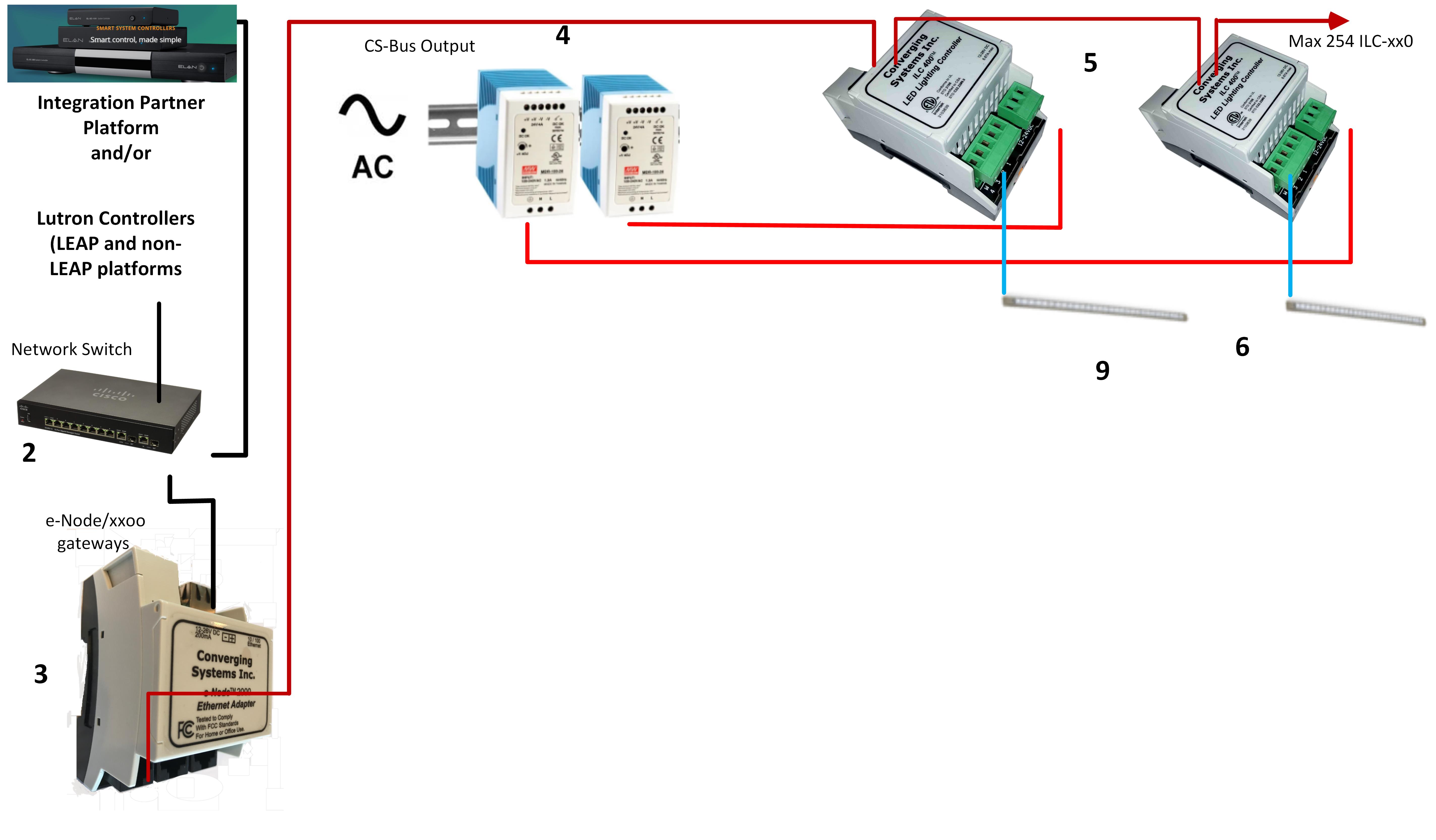
CS-Bus Wiring Considerations

  1. Recommended Cable Lengths? 

    The CS-Bus can be run up to 4000 feet using CAT5 or better wire properly wired with twisted pairs on pins (1/2), (3/4), and (5/6).

  2. RJ-25 Modular Connectors? 

    RJ-25 (6P6C) modular connectors are required to terminate onto the end of the twisted pair CAT able. We recommend you simply cut the two brown wires as far back as possible so that you can insert the remaining 3 twisted pairs into RJ-25 connector. These module connectors are readily available from Amazon for overnight delivery.

  3. CS-Bus Ports (Port 1 versus Port 0)? 

    There are two 6P6C (RJ-45) ports on each ILC-xx0. Port 0 is located on the left of the two ports and it is the powered port, while Port 1 on the right of the two ports is the non-powered port. It is important when wiring multiple ILC-xx0 to each other that you connect a Port 1 (on one device) to a Port 0 (on the next device) from the first/head-end ILC-xx0 to the last/tail-end ILC-xx0. It does not matter how you start the process, but just the sequence going the same way throughout the entire end-to-end daisy chain system. If connecting a keypad, refer to the keypad section for more detailed wiring information here.

  4. Testing? 

    It is recommended a standard cable tester that can test 6P6C connections (those same testers test RJ-45 wiring as well) be used to save much diagnostics time should there be an faulty crimp.

Related Articles:

  • ILC-xxx Family Quick Reference Installation Guide
  • Planning Document for ILC-xx0 Controllers
  • Power Distribution and DIN-Rail Chassis Mounting
  • e-Node Quick Reference Guide

  • Home
  • About
  • Where to Buy
  • Contact
  • Trade | Contract | Press
  • Integration Resources
  • Press
  • Catalog
  • Subscribe to Newsletter

  • © Copyright Converging Systems Inc.
    • Privacy Policy
    • Warranty