ILC-xx0 Backgrounder
Overview
- Key Features
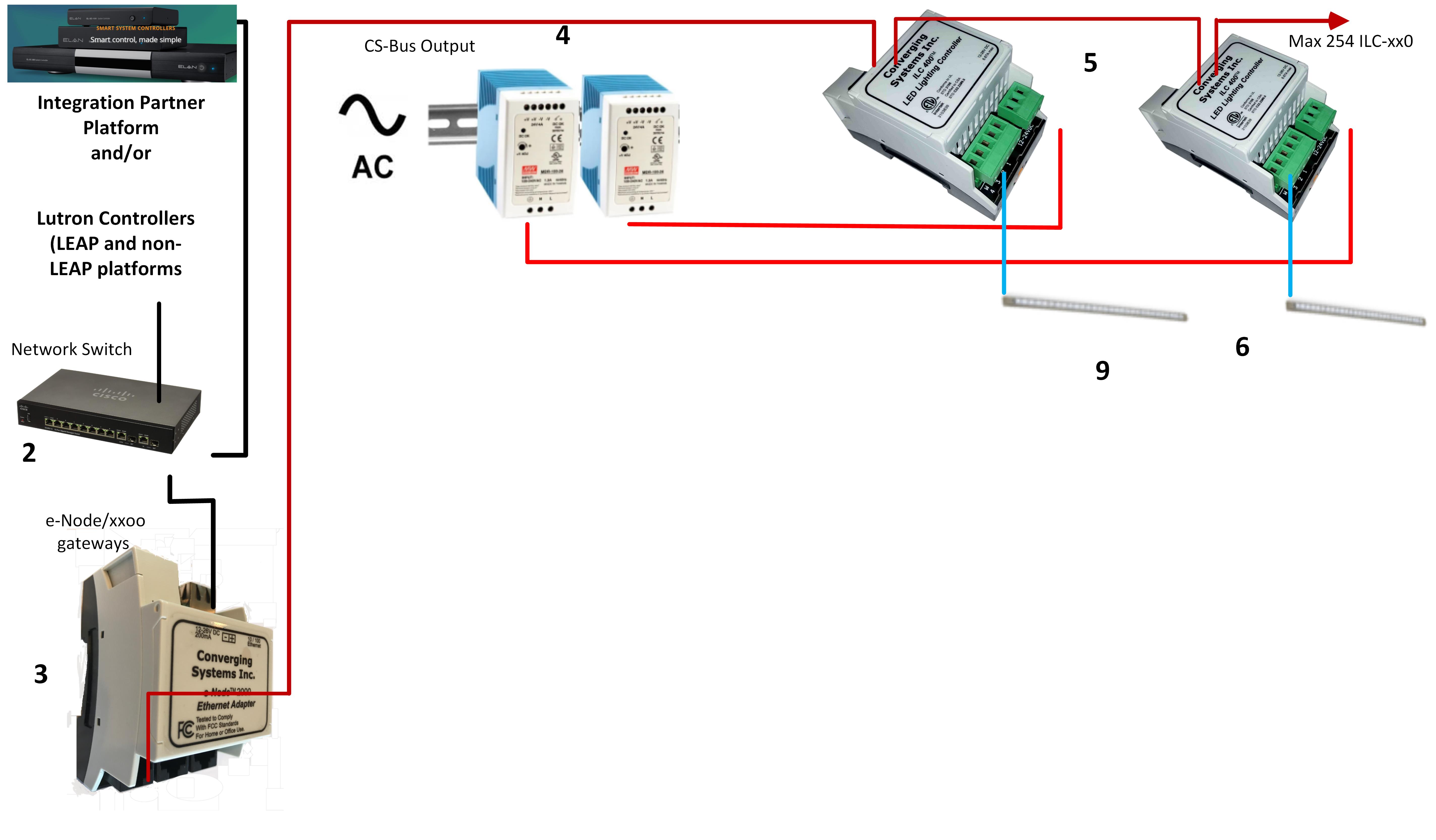
The CS-Bus can be run up to 4000 feet using CAT5 or better wire properly wired with twisted pairs on pins (1/2), (3/4), and (5/6). The CS-Bus is a derivative of a RS-485 network.
- Types of Lighting Devices Supported
Straight wiring. Typically this wire color coding should be sued. Pin 1 Blue, Pin 2 Blue/White, Pin 3 Orange, Pin 4 Orange/White, Pin 5 Green, Pin 6 Green/White. The CS-Bus can be run up to 4000 feet using CAT5 or better wire properly wired with twisted pairs on pins (1/2), (3/4), and (5/6). Do not use 568A or 568B wiring as this does not permit a twisted pair on pins 3/4 (of the 6 wires being used on the RJ-45 6P6c connector).
- Commissioning.
The system must be setup and commissioned (addresses given) to each ILC-xx0 in order for any light output to occur.
What is the required BOM to enable system operation?
- Minimum Requirements for Hardware to complete installation.
- Front-end Gateway (for connection to a Local Area Network).
- e-Node 2000 for connectivity to all lighting/automation platforms except for Lutron LEAP protocol devices
- e-Node 4000 for connectivity to all of the above plus all Lutron LEAP protocol devices (RadioRA3,Homeworks QSX,and Athena)
- Constant Voltage Linear Strips.
- Power Supply Unit (PSU) (rated Class 2) typically running at 24vDC/ ~96 watts.
- Line cord to connect PSU to standard electrical outlet (or direct wired to AC circuit by Class 1 electrician).
- CAT5 or better communication wire to connect e-Node/xx to first ILC-xx0 device and downstream from first ILC-xx0 (if there are additional ILC-XX0 units).
- RJ-25 (6P6C modular connectors) necessary to crimp on ends of CAT5 cabling (for interconnection between e-Node and ILCs).
- Electrical box with the ability to house DIN-rail components (and at least 4.17" deep to accommodate DIN-Rail PSU and ILC-xx0 devices).
What tools are suggested for an efficient installation
Suggested Tools/Equipment.
- RJ-25/RJ-45 crimper devices.
- PC Computer (preferred for accessing the WEB-based setup software).
- Internet connectivity (for e-Node).